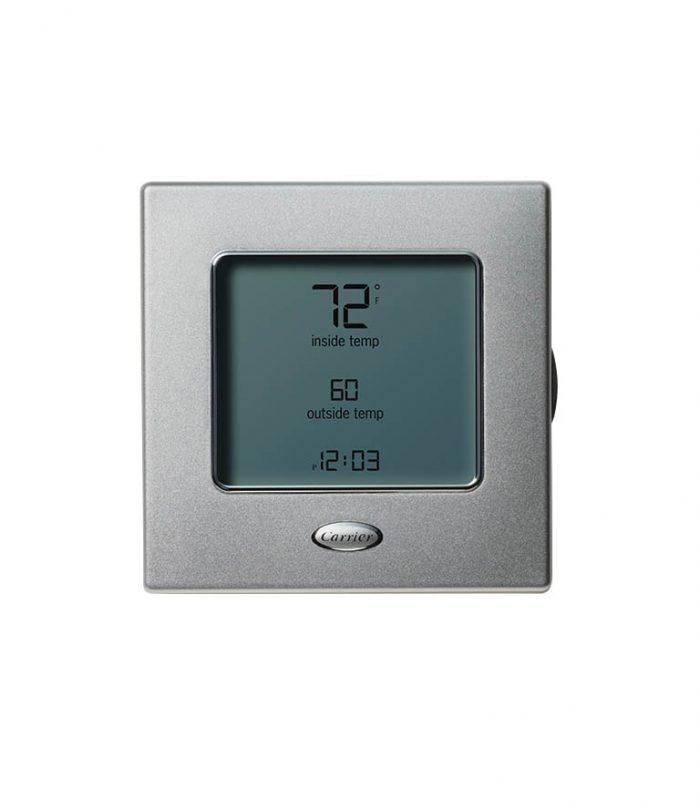
Find Older Carrier Thermostat User Manual
Programmable Thermostats
Installation, Start-Up, and Operating Instructions
NOTE:
Manual For Carrier Thermostat
Carrier offers thermostats and controls for the highest degree of climate control, from temperature to humidity, while staying energy efficient. Carrier’s 7-day programmable thermostats are wall-mounted, low-voltage thermostats which maintain room temperature by control-ling the operation of a heating and air conditioning system. Separate heating and cooling setpoints, plus auto changeover allow setback programming for maximum energy savings.
Read the entire instruction manual before starting the
Find programmable digital thermostats and more HVAC thermostats, controls and zoning at Carrier Enterprise. We provide owner manuals for all our major manufacturers. Click on a link below to download a PDF version of the manual for your specific product. If the owner manual you’re looking for is not listed below, we recommend visiting the manufacturer’s website. Find the user manual you need for your home appliance products and more at ManualsOnline. Carrier Thermostat Thermostat User Manual. Oct 23, 2017 Learn more about our products at Subscribe on YouTube: https://www.youtube.com/channel/UCr8Ue7woBYyFF5Ki1JamUQQ?subconfirmati.
installation.
This symbol
→
indicates a change since the last issue.
INDEX
Page
SAFETY CONSIDERATIONS ...........................1
INTRODUCTION .....................................1
INSTALLATION CONSIDERATIONS ....................1
INSTALLATION...................................2-12
Location...........................................2
Set DIP Switches ...................................2
Install Thermostat .................................2-3
Set Thermostat Configuration ........................3-4
Check Thermostat Operation ........................4-5
Final Settings ......................................5
Checklist..........................................5
WIRING DIAGRAMS ...............................6-12
OPERATIONAL OPERATION .........................13
TROUBLESHOOTING ................................13
CONFIGURATION RECORD..........................14
SAFETY CONSIDERATIONS
Read and follow manufacturer instructions carefully. Follow all
local electrical codes during installation. All wiring must conform
to local and national electrical codes. Improper wiring or installa-
tion may damage thermostat.
Recognize safety information. This is the safety-alert symbol
.
When you see this symbol on the equipment and in the instruction
manual, be alert to the potential for personal injury.
Understand the signal words DANGER, WARNING, and CAU-
TION. These words are used with the safety-alert symbol. DAN-
GER identifies the most serious hazards which will result in severe
personal injury or death. WARNING signifies a hazard which
could result in personal injury or death. CAUTION is used to
identify unsafe practices which would result in minor personal
injury or product and property damage.
INTRODUCTION
Carrier’s 7-day programmable thermostats are wall-mounted, low-
voltage thermostats which maintain room temperature by control-
ling the operation of a heating and air conditioning system.
Separate heating and cooling setpoints, plus auto changeover allow
setback programming for maximum energy savings. All of the
thermostats allow up to 4 time/temperature settings to be pro-
grammed per 24 hr period and store programs for 7 independent
days. Batteries are not required; during a power interruption, the
internal memory stores programs for an unlimited time and the
clock continues to run for at least 72 hrs.
INSTALLATION CONSIDERATIONS
Power
Note that all TSTAT models require no batteries and are not
'power stealing'. They do require 24VAC (R and C terminals) to
be connected for proper operation. Thermostat will not operate
without these 2 connections.
Models
There are 3 different models. The 9th and 10th letters of the part
number indicate the model. These 2 letters appear on the package
and on the circuit board. Be sure to have the proper thermostat for
the intended application. Models are:
AC - 1-stage cool, 1-stage heat - for AC systems only.
HP - 1-stage cool, 2-stage heat - for either HP or AC with 2-stage
heat.
2S - 2-stage cool, 2-stage heat - for 2-speed AC systems, or

2-stage cool, 3-stage heat - for 2-speed HP systems, or
1-stage cool, 4-stage heat - for 1-speed HP with special
3-stage electric heat.
Use each only for its intended purpose. (See Table 1.)
Outdoor Temperature Sensing
All Carrier programmable thermostats may be equipped with an
optional
outdoor
temperature
sensor,
Part
No.
TSTATXXSEN01-B. If it is to be used, plan installation so that 2
wires can be run from the thermostat to an outdoor location,
preferably on the north side of the house OR refer to Installation
Instructions included with the outdoor temperature sensor for
simplified connection. Sensor can be mounted to outdoor unit and
existing control wires used for its connection. Details are provided
to the sensor instructions.
INSTALLATION
Step 1—Thermostat Location
Thermostat should be mounted:
•
Approximately 5 ft (1.5m) from floor.
As an ENERGY STAR Partner, Carrier Corporation has
determined that this product meets the ENERGY STAR
guidelines for energy efficiency.
→
Fig. 1—Carrier Programmable Thermostat
A98426
HEIGHT (IN.)
WIDTH (IN.)
DEPTH (IN.)
4-1/4
7-1/2
1-3/8
Visit www.carrier.com
Manufacturer reserves the right to discontinue, or change at any time, specifications or designs without notice and without incurring obligations.
Book 1
4
Tab
misc. misc.
PC 101
Catalog No. 03TS-TA2
Printed in U.S.A.
Form TSTAT-15SI
Pg 1
9-98
Replaces: TSTAT-10SI
→
TB---PAC
TB---PHP
Base Series Programmable Thermostats
Homeowner’s Guide
Designed and Assembled

in the USA.
A07107
Base Series Programmable Thermostat
SETTING TIME AND DAY
At Power Up
When power is first applied, AC or HP will appear for 5 seconds to
tell you it is an air conditioner (AC) or a heat pump (HP) model.
After this, the time display will flash to tell you the power has been
off.
Setting The Current Time:
1. Press the TIME/TEMP button. SET TIME flashes on the
display.
2. Press the UP or DOWN button until the correct time is dis-
played.
3. To quickly advance to the proper time, press and hold the
UP or DOWN button.
4. When the correct time appears on the display, press the
HOLD/END button.
NOTE: If you choose not to press the HOLD/END button, the
thermostat will automatically exit the time setting mode after 10
seconds.
Setting The Current Day:
1. Press the DAY button to advance to the correct day.
2. When the correct day appears on the display, press the
HOLD/END button.
MANUAL OPERATION
To Operate Manually (Without the Programmed
Comfort Schedule):
Press the HOLD/END button to make the HOLD icon appear.
Then follow the four steps below:
1. To Select the Mode:
Use the H/C button to move between the choices. OFF,
HEAT, COOL, or EMHT will appear on the display. EMHT
will only appear on heat pump models.
2. To Select the Fan Operation:
Use the FAN button to move between continuous fan (in-
dicated by the FAN ON icon) and auto fan operation.
3. To Read the Room Temperature:
The large display reads room temperature until a button is
pressed.
4. To Adjust the Setpoint:
In normal operation, the large display shows room temper-
ature. At the first press of the UP or DOWN button, the
large display shows the current setpoint and the SET TEMP
icon is turned on. Further presses of the UP or DOWN but-
ton adjust the setpoint upward or downward. Five seconds
after the last button press, the display returns to the room
temperature and the SET TEMP icon turns off.
PROGRAMMED OPERATION
Introduction
The Base Series Programmable Thermostat provides four periods
per day (MORNING, DAY, EVE, NIGHT) and two schedules per
week (MoTuWeThFr and SaSu). A separate time, heat setpoint,
and cool setpoint can be set for each period and schedule. Before
starting to actually program the thermostat, fill out Table 1 with the
values you wish to program. (The Energy Starr, US Department of
Energy recommended time and temperature values are already
programmed for you as a starting point and are shown on the left
End user manual for sap pm. Jan 21, 2017 This training document provides instructions for most common end user functions listed below in SAP’s Plant Maintenance (PM) module: Creating a Functional Location Creating a Piece of Equipment Displaying the Structure List and the Structure Graphic Creating Data for the Permit Maintaining Bills of Material Creating Maintenance Task Lists Creating Operations / Sub-Operations. Jul 18, 2013 In this post, you will find download links for seperate SAP PM End user Training Manuals of the each processed below described: Preventive Maintenance process: This manual consists of the following sequence of sub-processes Task List availability check IA02 Maintenance Plan IP02 Scheduling of Maintenance Plan IP30 Scheduling overview IP24 Order details IW32 Assigning.
side of the table.)
The first press of the PROGRAM button brings up the
programming mode and places you at morning of the current day
and period. Successive presses move you between the four daily
periods.
While Programming:
The TIME/TEMP button moves between three selections of SET
TIME, SET TEMP & HEAT, and SET TEMP & COOL. These
three numbers are to be programmed for each of the periods
MORNING, DAY, EVE, and NIGHT.
The DAY button moves between the weekdays, (MoTuWeThFr)
and the weekend (SaSu) selections. A different schedule may be set
for the weekdays and the weekend. You may exit programming at
any time by pressing the HOLD/END button.